Thursday, May 18, 2017

Optical Lens Coating Technology and Development

In daily use, the friction with dust or grit (silicon oxide) will cause the inorganic or organic materials made glasses lens scratched the surface. Compared with the glass, the hardness of organic materials is relatively low, it is easier to be scratched. Through the microscope, we can observe the surface of the lens scratches can be divided into two types, one is caused by the gravel, shallow and small, no easy to be detected by the wearer; another is caused by the large gravel, deep and periphery rough, and it will affect the vision when it is in the central region.
 

Technical characteristics

1. The first generation wear resistant film technology
Wear resistant film began in the early 1970s. At that time the optical lenses are not easy to be ground because of its high hardness, while the organic lens is too soft and easy to wear. So they plate the quartz material on the surface of the organic form under the condition of vacuum, forming a layer of hard abrasion resistant film. But due to the mismatch of thermal expansion coefficient and the base material, it is easy to strip and the film is brittle, so wear resistant effect is not ideal.

2. The second generation wear resistant film technology
After the 1980s, the researchers found theoretically that the wear production mechanical is not only related to hardness. The coating material has dual characteristics of hardness/deformation, namely, some materials are with high hardness, but the deformation is smaller, and some materials are with low hardness, but deformation is large. The second generation of wear resistant film technology is coating a high hardness and non-fragile material on the surface of the organic lens by soaking process.

3. The third generation wear resistant film technology
The third generation of wear resistant film technology was developed in the 1990s. It is developed to solve the problem of the wear resistance of the anti-reflective coating on the organic lens. Because of the great difference between the organic lens hardness and anti-reflection film hardness, the new theory is that there is another layer of abrasion resistant coating between them, which will play a buffer role and no scratching occurs at the time of gravel friction. Between the third generation of wear resistant film material’s hardness is between anti-reflection film ‘s and lens substrate's, the friction coefficient is low and not easy to crack.

4. The fourth generation wear resistant film technology
Silicon atom is used in the fourth Fourth generation wear resistant film technology, for example, TITUS hardening liquid produced by the France Fishily company contain both organic substrates and silicon inorganic particles, makes the abrasion resistant film with the property of toughness and high hardness. The most important method of modern wear resistant film technology is immersion method, that is, after repeated cleaning, immerse the lens into plus hardening liquid for a period of time, raise up in certain speed. This rate is related to the viscosity of the hardening liquid and function decisively to the thickness of the film.  And then polymerize in the oven for about 4 to 5 hours at 100 degrees ℃, the coating thickness is about 3 - 5 microns.


Test method

1. Grinding experiment
Place the lens inside the gravel (the provisions of the size and hardness of gravel), and grind under the control. At the end of the test, measure the light ray diffuse reflection quantity using haze meter. and compared with the standard lens.

2. Steel wool test
Grind the lens a certain number times using the specified steel wood in certain pressure and velocity, and then measure the light ray diffuse reflection quantity using haze meter. and compared with the standard lens.  Of course, we can also manually grind two pieces of the lens using the same pressure with the same number of times, and then observe and compare with the naked eye.
The results of the above two methods are similar to those of the long-term clinical results.

3. The relationship between antireflection film and wear resistant film
The antireflection coating on the surface of the lens is a very thin inorganic metal oxide material (thickness less than 1 microns), hard and brittle. When the plating on the glass lens, because the base is relatively hard, gravel on it across, the film is not easy to be scratched; But if the antireflection film plated on the organic lenses, because the base is relatively soft, gravel in the coating, the film is easy to be scratched.
Therefore, in order to improve the hardness of the two kinds of coatings, it is necessary for the organic lens to be placed with the wear resistant film before the coating is reduced.

Labels: , ,

Wednesday, May 17, 2017

Optical System Design

The use of any kind of optical instruments and the conditions of use will certainly make demands on its optical system. Therefore, we must understand its requirements to the optical system before we carry out the optical design. These requirements are summarized in the following aspects.
18mm-microscope-objective-lens3

I. The Fundamental Characteristic of Optical System
The fundamental characteristic of optical system is: Numerical aperture or relative aperture; linear field or field angle; systems magnification or focal length. In addition, there are some related characteristics, such as, the size and location of pupil, working distance and conjugate distance.

II. The Systems Overall Dimension
The overall dimensions of the system, i.e., the horizontal and vertical dimensions of the system. In the design of complex optical systems. It is imperative that designers shall correctly define the compatibility of optical element groups pupil. 

III. Imaging Quality
Imaging quality requirements related to the use of optical systems. Classified by the applications use, there are different imaging quality requirements on different optical systems. For the telescope system and the general microscope, it is necessary to have a good image quality only in the central field of view. But for the photographic lens, the good quality requirement is needed to meet in the whole field of view.

IV. The Use Conditions of Instrument
When we propose to make the demand on the optical system the function of the, we must consider the possibility of the feasibility of both technical and physical aspects realization. Such as biological magnification should fit into the range of be among 500NA≤Г≤1000NA, when we develop telescope system, in terms of consider the telescope visual magnification, the resolution limit of both telescoping system and human eyes must be taken into consideration.

The Design Process of Optical System
Optical system design is the process of determining a variety of data on the basis of use conditions and meets the application imaging quality use requirements, which is, determining the performance parameters of the optical system, the overall dimensions and the structure of the optical element group, etc. Therefore, the optical design process can be divided into 4 stages: the dimension calculation, the initial structure calculation, the aberration correction and balance, and the image quality evaluation.
I. The Overall Size Calculation

At this stage , we need to draw up the design principle of optical system, determine the basic optical properties, which will meet a given technical requirement, that is, the magnification or focal length, lineal field or field angle, numerical aperture or relative aperture, conjugate distance, after working distance of diaphragm position and external dimension etc.. Therefore, this stage is often called the overall dimension calculation. Generally, we calculate the overall dimensions according to perfect optical system theory and calculation formula. And in the process, the mechanical structure and electrical system must be considered in order to prevent the occurs of the infeasible structure. The determination of each performance must be reasonable, if it is too high,  the design results will be wasted, if it is too low, the design will not meet the requirements, so this step is needed to be considered carefully.

II. The Calculation and Selection of the Initial Structure
The following two methods are usually used to determine the initial structure:
1. Solve the primary aberration theory according to the initial structure.
The method of solving the initial structure is based on the fundamental characteristics calculated from the overall dimensions, and the primary aberration theory is used to solve the initial structure which meets the image quality requirements.
2.Solve the initial structure from the existing document
This is a practical and easy to achieve methods. So it is widely used by many optical designers. But it requires designers to have a deep understanding of the theory of optics, and has a wealth of experience in design. Only this, can he pick out a simple and demanding initial structure from a wide range of structures. The choice of the initial structure is the basis of the lens design. A bad initial structure, no matter how good the automatic design process and experienced designers can not make the design successful.

III. The Aberration Correction and Balance
After the initial structure is selected, the optical path is calculated on the computer with the optical calculation program, and all the aberration and the aberration curves are calculated. According to the analysis of aberration data, it is possible to find out which aberration is the main influence on the imaging quality of optical system. And then, we can find out the modified methods and correct the aberration. Image difference analysis and balance is an iterative process until the image quality requirements are met.

IV. The Image Quality Evaluation
The imaging quality of the optical system is related to the size of the aberration. The purpose of the optical design is to correct the aberration of the optical system. However, it is not possible for any optical system to adjust all the aberrations to zero, and the existence of residual aberration is inevitable. Therefore, the optical designer must have the knowledge of the tolerance value of the optical system’s residual and the aberration tolerance, so as to judge the imaging quality of the optical system according to the residual aberration. There are many methods to evaluate the imaging quality of the optical system. We will briefly introduce the aberration evelation method

1. Rayleigh’s Judgment
The largest wave aberration between the actual wave surface and the ideal wave surface is not more than 1/4 wavelength. It is a more rigorous method to evaluate image quality, which is suitable for small aberration system, such as telescope, micro-objective and so on.

2. Resolution
Resolution refers to the optical system’s ability in terms of distinguishing the object’s details . When the center of the diffraction image of a point coincides with the first dark ring of another point, it is precisely the boundary of the two points that can be separated.

3. Diapoint
When a lot of light emitted by a point go through the optical system, the aberration will cause the intersection between the light and the image plane not focus on the same point, and forming a dispersed graphics within a certain range, called the diapoint. It is usually used as a practical and effective dispersion spot with a concentration of more than 30% points or a circle of light. The reciprocal of its diameter is the number distinguished by the system. It is generally used to evaluate the large aberration system.

4.  Optical Transfer Function
This method is based on the theory that the object is composed of the spectruma with variety of frequencies, that is, the object's brightness distribution function expands as the Fourier series or Fourier integral. The optical system is regarded as a linear invariant system, so that the image of an object through an optical system can be regarded as the transmission of a series of linear systems with different frequencies. Transmission is characterized by the same frequency, but declining contrast, the moving phase to a certain frequency. The decrease of contrast and the change of phase vary with frequency, and the relation between them is called optical transfer function. Because the optical transfer function is related to the image difference, it can be used to evaluate the imaging quality of optical system. It is objective, reliable, and easy to be calculated and measured. It is not only be used to evaluate the results of optical design, but also to control all aspects of the optical system design, optical lens inspection and the process of general design .
dual-fisheye

The Design Difference Among Different Kinds of Lens

I. Camera lens
The optical properties of the camera lens can be represented by three parameters: the focal length of the camera lens F', the relative aperture D/f' and the field angle (2 Omega). In fact, in terms of 135 cameras, its standard frame has been determined as 24mm X 36mm, the diagonal length is 2D=43.266. From the following table we can see that there is a relationship between the focal length of the camera lens and the field angle f': tgω'=D/f'
In this formula: 2D - diagonal length of frame;
F'- focal length of lens.

Another important optical feature of the camera lens is the relative aperture. It represents the ability of the lens to pass through the light, expressed in D/f'. It is defined as the ratio of the lens aperture diameter (also known as pupil diameter) D and lens focal length F'. The reciprocal of the relative aperture is known as the aperture factor or aperture of the lens, also known as the F, that is, F=f'/D. When the focal length F'is fixed, the F is inversely proportional to the pupil diameter D. Because the area of the light is proportional to the square of the D, the larger the area of the light, the greater the luminous flux of the lens. Therefore, when the number of apertures is in the smallest value, the hole is in its largest value, luminous flux is also the largest. With the increase of the number of apertures, the light hole becomes smaller and the luminous flux decreases. If you do not consider the impact of different lens with transmittance differences, no matter how long the lens focal length is, regardless of how far the lens aperture diameter is, as long as the aperture values are the same, they have the same luminous flux. Compared with the camera lens, F is a very important parameter, the smaller the F value , the wider the scope of the lens.
Compared with the visual optical system, camera lens have a large relative aperture and large field of view, therefore, in order to see the clear and object plane similar image on the whole image plane, almost all the seven kinds of aberration need to be corrected. The resolution of the photographic objective lens is a comprehensive reflection of the relative aperture and aberration residue. After the relative aperture is determined, the optimal error correction scheme is developed, which can meet the requirements and is easy to realize. For convenience, Disperse spot radius is often used to measure the size of the aberration, and the optical transfer function is used to evaluate the image quality.

In recent years, the rising digital camera lens is similar with the traditional camera lens in the aspects of design evaluation and properties, the main difference is:
1 relative aperture is larger than traditional camera.
2 short focal length causes the depth of field increases. According to the size of the field angle, we can calculate the equivalent of the traditional camera lens focal length value F '=43.266/ (2*tg).
3 high resolution, according to the size of the PIXEL in the photoelectric device, the general digital lens optical design will achieve 1/ (line) pairs.

II. The projection lens
The projection lens refers to the illuminated object will form a bright and clear image on the screen. Generally speaking, image distance is much larger than the focal length, so the object plane is near the focal plane of the projection lens.
The magnification of the projection lens is an important parameter of the measurement accuracy, aperture size, observation range and structural size.
The larger the magnification, the higher the accuracy of the measurement, the larger the aperture of the lens. When the working distance is constant value, the larger the magnification is, the larger the conjugate distance is, the larger the projection system size. According to the knowledge of optics, the illumination of the image center is proportional to the square of the relative aperture. So the method of increasing the relative aperture can be used to increase the illumination of the image surface.

The difference between the projection lens used in liquid crystal projector and the traditional projection objective:
1 larger relative aperture.
2 pupil distance is longer, need to be designed as Jinyuanxinlight path.
3 long working distance.
4 high resolution.
5 high distortion requirements
The above points causes the projection objective used for LCD projectors is much more complex than the traditional, It is about 10 lenses compared with the traditional 3 lenses. 

III. F-theta lenses
F-theta lenses can be represented by three optical properties, i.e., relative aperture, magnification and conjugate distance. The magnification is an important index of F-theta lenses, because the object size is fixed, the smaller the magnification is , the smaller the lens image plane is, the shorter the focal length is . So the scanning system structure can be made smaller, but the resolution of the lens is requires to be  higher. Conjugate distance refers to the length of the objective image. For lens,the longer of the lens and the shorter the conjugate, the difficult the design of lens is.The schematic diagram, like a photographic objective, is a narrowing process.

optical-structure-1

Design Features of F-theta lenses:

1 F-theta lenses belongs to a small aperture, small aberration scope. It has high requirements on optical resolution  .
2 due to the photoelectric device, it not only correct the white (mixed light) aberration, but also need to consider the R, G, B three independent wavelength aberration.
3 strictly corrected distortion aberration.

Labels: , , ,

Pieces Knowledge: Basic Knowledge of Optical Lens Grinding Process

I. The grinding purpose and fundamental principle

1. Purpose:
(1) to remove the damaged layer of fine grinding to meet the requirements of the specified appearance limit
(2) To finish the surface, let curvature radius R circular reaches a specified value, meet the requirements of the number of NR and the local curvature of the aperture tolerance (Yasi).
2. Fundamental principle
By mechanical movement, the mechanical action will occur between the grinding agent and the glass in the grinding dish. And the purpose of precision polishing will achieve.


II. the types and use of the required dish

1 grinding dish: used for grinding lens
2 fixture: used to hold the optical lenses for fine grinding
3: relay equipment: the joint between machine and grinding dish, the height and coaxiality is adjustable.
4 dishes: used to repair the accuracy of the drill plate
5 drilling dish: it is used to correct the precision of grinding plate (drilling dish is by diamond particles curvature surface sticking into or out of shape curvature surface, its accuracy is generally +2 dish, dish 0~-1 negative, it is used for repairing and grinding the skin)

III. The main control point for grinding

1. Check the fixed points, scars, sand, broken, frog skin, corrosion on the surface or not.
2. Check the quantity of Yasi, vertical edge, the number of the surface is under the limit or not.
3. Check the grind quantity is in the within standard or not.
  • The Yasi ---- surface precision deviation image circle of confusion  (ellipse, saddle-shaped, pillar), local irregular aperture (middle part high, middle part low, vertical edge)
  • Middle part high---When the lens and the original contract fully, a small aperture will be thick, when we pull the edge,  the center will hump inward, pull 1/2, an ellipse will occur.
  • Middle part low - when the lens and the original contract fully, the center of the aperture gap is too narrow, too dense. When we pull the edge, the central bulge outward, pull 1/2, the ellipse will appear.
  • Corrosion, usually referred to as corrosion, is the appearance of a massive, punctate, fog like phenomenon caused by the chemical reaction between the surface of optical lenses and water or other substances in the air.

Achromatic Doublet Lenses

Achromatic Doublet Lens

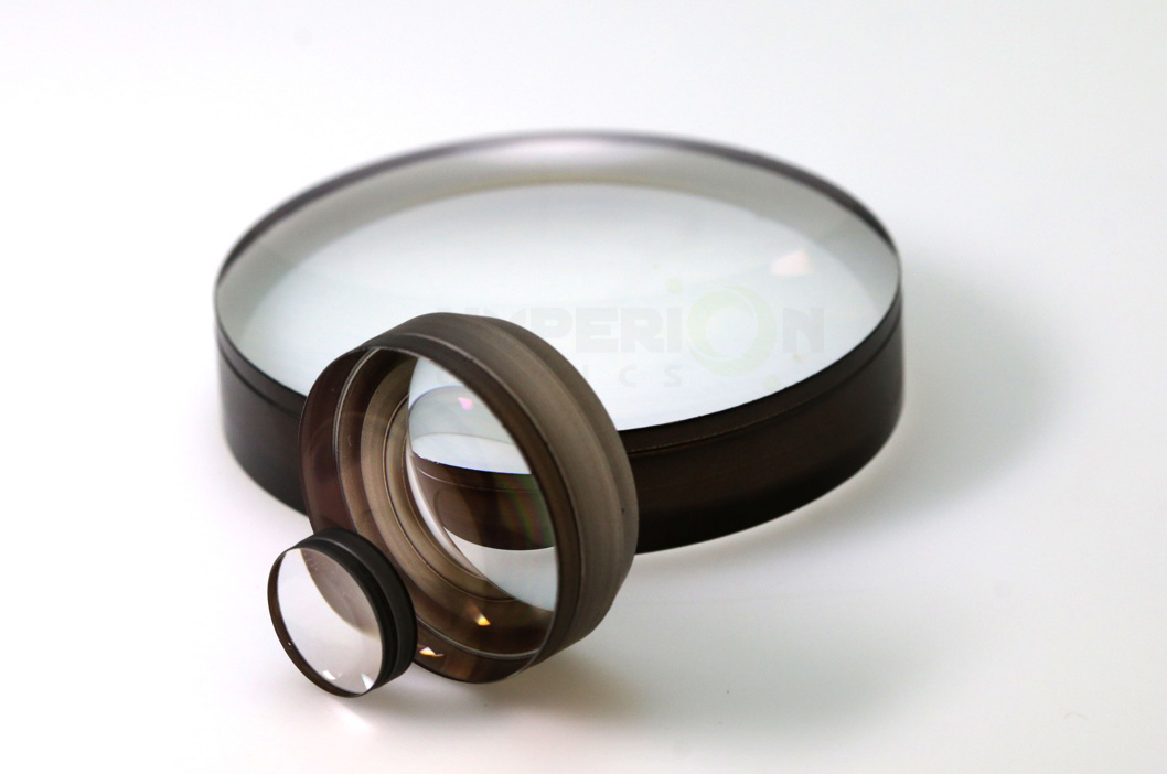
At Hyperion Optics, with decades fabrication experiences, we have been providing our customer a vast number of achromatic lenses for their applications in different precision grades, please check our test plate radius available online for download to save your cost on custom achromatic doublet lens optical design. Particularly for cost-sensitive design, our series production capability always ensures a satisfying pricing solution.

As optical designers widely use doublets which contribute latitude to eliminate chromatic and spherical aberrations more thoroughly. We also provide excellent suggestions for glass material selection in individual design as we distinguish the importance of refractive index precision in material selection stage despite the design data in software.

Universally, with particular flint glass designers might choose, certain glass’ deliquescence attribute lead to cosmetic failure after polishing, or even affect the transmission after coating. Let us help to avoid such problem in your design to live process.


COMMERCIAL GRADE
FACTORY STANDARD
PRECISION GRADE
Diameter Tolerance(mm)
±0.05
±0.03
±0.0125
Center Thickness(mm)
±0.01
±0.03
±0.025
Radius (%)
±1%
±0.5%
±0.3%
Focal Length Tolerance (%)
±3%
±1%
±0.5%
Cosmetic(MIL-C-13830A)
100-80
40-20
10-5
Figure Tolerance in λ(Pow/irreg)
3 - 1
2 - 1/4
1 - 1/10
Centration (Arc min)
6
<3
<1
Dia. To Thick Ratio
9~50:1
Coating (T% avg)
96-98%
99%
99.5%
Materials


For extremely precision sensitive system requirement, please contact us for further information, our engineers are more than happy to evaluate your design and have our experiences of manufacturing input help to define the most appropriate tolerances.

Labels: , , , ,

Tuesday, May 9, 2017

Optical lens design for adaptation of traditional lights to LED

ABSTRACT

An Italian company operating in the field of renewable energy has developed a system to customize traditional lights adapting them with LED lighting. The company is looking for research institutes that can develop further applications (i.e. optical lens design for LED lighting) under technical cooperation agreement.

FULL DESCRIPTION

The company's activity concerns the customization of traditional lights adapting them with LED lights technology. 

LED lights technology can offer the advantage to have high reduction of energy consuming compared with traditional lights or energy saving lights. Another advantage of the LED technology is its long life. LED bulbs have an outstanding operational life time expectation of up to 50.000 hours. This is around 17 years considering 8 working hour per day before one would have to replace the LED bulb.
LED lights are also eco-friendly because they are free of toxic chemicals. Most conventional fluorescent lighting bulbs contain a multitude of materials like e.g mercury that are dangerous for the environment. LED lights contain no toxic materials and are 100% recyclable. The long operational life time span mentioned above also means that one LED light bulb can save material and production of 25 incandescent light bulbs.
Also, LED lights can switched off and on frequently and without affecting the LED’s lifetime or light emission. In contrast, traditional lighting may take several seconds to reach full brightness, and frequent on/off switching does drastically reduce operational life expectancy.
During the design stage the company considers the wattage and the luminous flux of the original lamps, the type of LED to install can this be chosen.

The aim of the company is to offer specific products for customers' needs; thus, they are seeking collaborations with institutes under technical cooperation agreement. The ideal partner would be able to develop specific applications like for example optical lens for LED lighting. A lens is an optical device which transmits and refracts light, converging or diverging the beam. A simple lens consists of a single optical element. A compound lens is an array of simple lenses (elements) with a common axis; the use of multiple elements allows more optical aberrations for correction than what would be possible with a single element. Lenses are typically made of glass or transparent plastic.
Commercial LEDs are usually provided with an optical lens with beam angle of 120°. This characteristic could be a limit of the LED lighting. Depending on the ambiance to illuminate, a customer could need a spot light or a light with an wider angle. According to the company's policy of customers support in their specific needs, the company is seeking for University and R&D institutions to collaborate with to develop optical lens with different beam angle.

Partner expertise sought:

- Type of partner sought: Others important aspects to consider are the Colour Temperature (CCT), according to the ambiance where the lamp will be installed, and the Colour Rendering Index (CRI)
One more important aspect to consider is the heat sink, whose design is basic for the life span of the LED. 
- Specific area of activity of the partner: The company is looking for research institutes that can develop further applications and adaptation of traditional lights to LED lights technology (i.e. optical lens for LED lights, OLED applications) under technical cooperation agreement. 

Labels: , , ,

Advances in lenticular lens arrays for visual display

Lenticular lens arrays are widely used in the printed display industry and in specialized applications of electronic displays. In general, lenticular arrays can create from interlaced printed images such visual effects as 3-D, animation, flips, morph, zoom, or various combinations. The use of these typically cylindrical lenses arrays for this purpose began in the late 1920's. The lenses comprise a front surface having a spherical crosssection and a flat rear surface upon where the material to be displayed is proximately located. The principal limitation to the resultant image quality for current technology lenticular lenses is spherical aberration. This limitation causes the lenticular lens arrays to be generally thick (0.5 mm) and not easily wrapped around such items as cans or bottles. The objectives of this research effort were to develop a realistic analytical model, to significantly improve the image quality, to develop the tooling necessary to fabricate lenticular lens array extrusion cylinders, and to develop enhanced fabrication technology for the extrusion cylinder. It was determined that the most viable cross-sectional shape for the lenticular lenses is elliptical. This shape dramatically improves the image quality. The relationship between the lens radius, conic constant, material refractive index, and thickness will be discussed. A significant challenge was to fabricate a diamond-cutting tool having the proper elliptical shape. Both true elliptical and pseudo-elliptical diamond tools were designed and fabricated. The plastic sheets extruded can be quite thin (< 0.25 mm) and, consequently, can be wrapped around cans and the like. Fabrication of the lenticular engraved extrusion cylinder required remarkable development considering the large physical size and weight of the cylinder, and the tight mechanical tolerances associated with the lenticular lens molds cut into the cylinder's surface. The development of the cutting tool and the lenticular engraved extrusion cylinder will be presented in addition to an illustrative comparison of current lenticular technology and the new technology. Three U.S. patents have been issued as a consequence of this research effort.
© (2005) COPYRIGHT SPIE--The International Society for Optical Engineering. Downloading of the abstract is permitted for personal use only.

Labels: , , , , , , , , ,

Monday, May 8, 2017

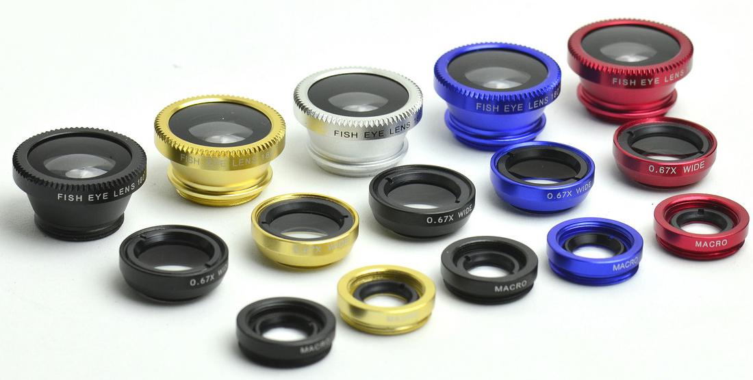
Exclusive Distributor Of ICO Smart Phone Attach-on Lenses


Hyperion Optics is the exclusive distributors of ICO cell phone attach-on fisheye lenses, wide FOV lenses, please contact our sales for further information.
Exclusive Distributor Of ICO Smart Phone Attach-on Lenses

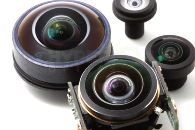
Fisheye Lenses

Fisheye Lenses

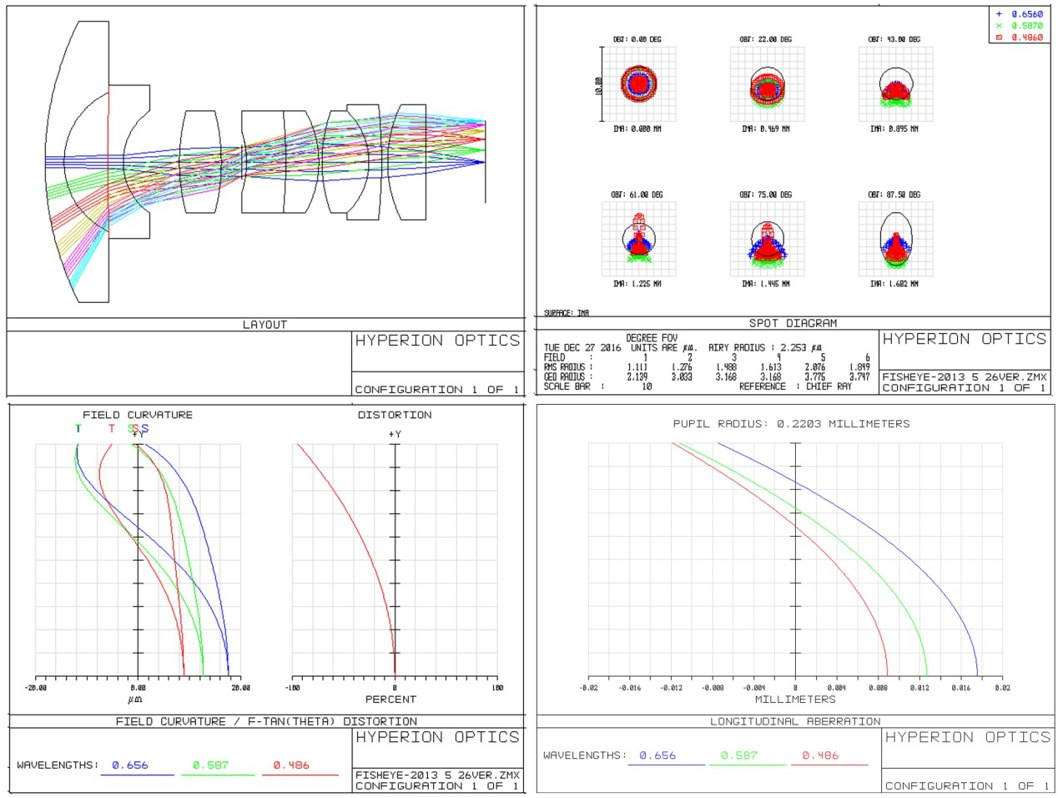
Typically fisheye lens has a front lens group of a greater negative refractive power than an ordinary inverted telephoto wide angle lens, with a large back focal distance. Its extreme power distribution will cause great field curvature in the transmitted image. As fisheye lens leads to significant barrel shaped distortion, to improve field curvature and astigmatism, it is necessary to compose a doublet to avoid significant negative deviation and provide correction of chromatic aberration.

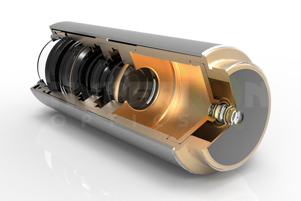
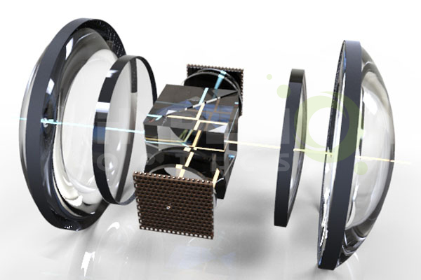
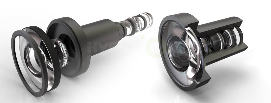
Hyperion Optics designers’ expertise contributes various range of fisheye lenses customized projects, from sminiature fisheye lense used for 360 degree viewing device to 200mm in diameter dome projection fisheye lenses. Our fisheye lens database provides design result and simulations for full frame fisheye lenses, circular image (hemispherical) fisheye lenses with different focal length options.
Hyperion Optics design

Hyperion fishy lense

During design process, our designers evaluate relative illumination performance by utilizing real ray trace analysis, vignetting is also used to control off-axis aberrations due to a half stop or full stop in relative illumination is tolerable in conventional photography scenario. Distortion departure from f-theta mapping is also critical in our design phase, according to the initial simulation and calculation; our designers are able to adjust and optimize to reach an ideal solution. We also look into lateral color which is the lateral shift on the image plane intersection between the shortest wavelength chief ray and the longest wavelength chief ray by real ray trace analysis.

Labels: , ,

Improved Diameter Tolerance Control

Hyperion Optics upgraded our edging device in spherical lens components manufacturing process, we now are able to provide +0/-0.01mm in diameter tolerance control for your precision demand. Please contact our sales if you have tight diameter parameter to deal with.

Improved Diameter Tolerance Control


Spherical Lenses

Singlet lens is a lens consisting of a pure single element, which can be considered as the fundamental element of developing optical systems. Based on optical engineers’ design, multiple singlet lenses might be utilized within an optical system with other optics.

As the basic optical element, singlet lenses are commonly used in engineers’ design, and further assembly works for a variety of applications such as imaging collimating. At Hyperion Optics, our manufacturing capability covers Plano-Convex/Concave, Bi-Concave, Bi-Convex, Positive and Negative Meniscus, ranged from many variations of optical glass and fused silica and even crystal. With our reliable coating technique, AR or V-coatings can be applied to reach expectation. Special treatment i.e. edge blackening / special packaging / labeling also available upon request.

Our singlet lenses production competency helps our customers to build their unique and cutting edge applications such as microscopy device, diameter 2.5mm~3.5mm design, for projection/ observation applications, we can deliver 180+mm in diameter singlet lens. Besides regular visible spectrum singlet lenses, NIR / SWIR/ MWIR / LWIR lenses are also available at our facility, please refer to our IR optics for more information.

For extremely precision sensitive system requirement, please contact us for further information, our engineers are more than happy to evaluate your design and have our experiences of manufacturing input help to define the most appropriate tolerances.

Labels: , , ,

Please Visit Us At OPTATEC 2018

Hyperion Optics will attend OPTATEC show 2018 , our booth number is J70, OPTATEC 15th-17th May 2018 Exhibition Centre Frankfurt, Germany Hall 3.0. We are looking forward meeting you at the show.
OPTATEC 2018

Labels: , , , ,

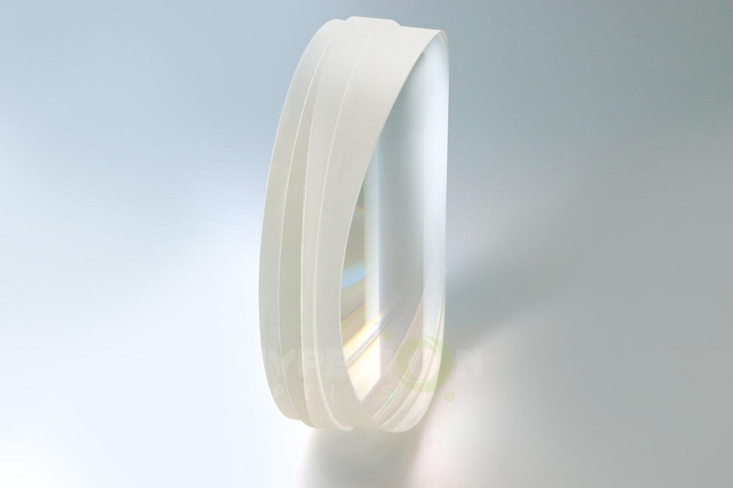
Calcium Fluoride Aspherical Components

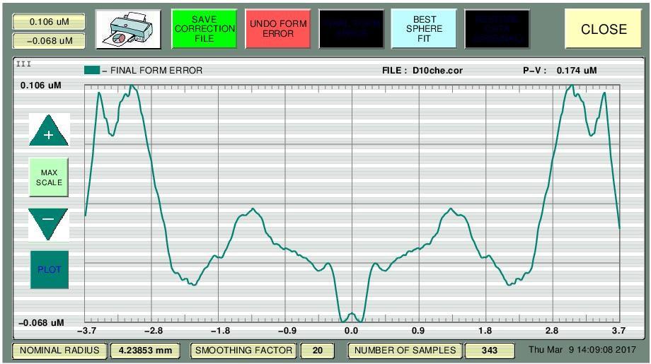
Hyperion Optics introducing CaF2 aspherical lenses with competitive prices. Especially for low volume prototyping projects. We are able to achieve 0.2-0.3 micron PV for the aspherical surface precision. Profile report can be provided.

Calcium Fluoride Aspherical Components

Labels: ,

Achromatic Cylindrical Lenses

Achromatic cylindrical lenses

Achromatic cylindrical lenses are ideal for eliminating spherical and chromatic aberration at the image plane, for example using monochromatic light source, achromatic cylindrical lenses can form a 50-90% smaller spot compared to singlet.

For most severe laser or imaging applications which involve cylindrical components, such as anamorphic projection, anamorphic photography, and achromatic cylindrical lenses are introduced. Hyperion Optics can manufacture based on custom design doublet or triplet achromatic cylindrical cemented lenses by using centering alignment device with UV curing unit to process precision bonding and testing at the same time. Every singlet is fully inspected before bonding.

anamorphic lenses

We are capable of producing up to 150mm in diameter with reliable anti-reflective coatings, centering strictly controlled on optical edging device, and surface accuracy is defined on Zygo. Further, we also help customer to adopt Chinese CDGM or NHG equivalents in achromatic cylindrical design, this is particularly flexible solution in LRIP cases.

Please check out our anamorphic lenses for more information. If you are in the stage of developing your own anamorphic lenses, don’t hesitate contacting one of our optical engineers for free consultation to receive assistant from manufacturing perspective. Talk to one of our skilled technicians for more details.

AchromaticCylindrical Lenses
COMMERCIAL GRADE
FACTORY STANDARD
PRECISION GRADE
Size Tolerance Length/Width(mm)
+0/-0.30
+0/-0.25
+0/-0.25
Diameter (mm)
+0/-0.15
+0/-0.10
±0.025
Wedge (along axis)
5 mrad
3 mrad
1 mrad
Focal Length Tolerance (%)
±2%
±2%
±1%
Cosmetic(MIL-C-13830A)
80-50
60-40
10-5
Irregularity (Lambda @ 632.8nm)
1 L
1/2 L
1/10 L
Centration (Arc min)
<5'
<3'
<1'
Coating (T% avg)
99%
99.5%
99.5%
Materials
Optical Glasses Depends On Design

Labels: , ,