Wednesday, November 8, 2017

The Application and Development of Cylindrical Lens in Modern Optoelectronic Products

The image monitoring and imaging devices currently being promoted provide us with an irreplaceable safety and comfort...
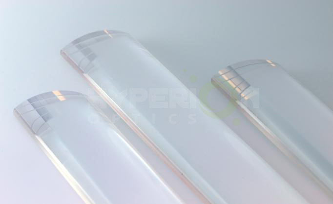
cylindrical lens 
Perhaps, while we are enjoying the convenience of optoelectronic products, we are ignoring the important components of the optoelectronic products, the cylindrical lens.

As we all know, Optoelectronic products are mostly composed of the light path system, electronics and mechanical systems. Light path system is considered to be crucial in the process of information collection and transmission. 

The optical system is composed of lenses, spectroscopes, and reflectors. The surface is usually a sphere or plane. The cylindrical lens is non-spherical, which can effectively reduce the ball difference and color difference. It is divided into flat convex cylindrical lens, flat concave cylindrical lens, double convex cylindrical lens and double concave cylindrical lens. It has one-dimensional amplification. Cylindrical lenses are designed to change the size of the image. For example, turn a spot of light into a patch or change the height of the image without changing the width. The special optical properties of the cylindrical lens make the cylindrical lens more and more widely used with the rapid development of high technology. Such as line gather system. films system. fax machines and printing typesetting scanning imaging system. And in the field of medical gastroscope. Laparoscopic, in the field of auto car video system with the participation of cylindrical lens. Linear detector at the same time in lighting, bar code scanning, holographic lighting, optical information processing, computer, laser emission. And the strong laser system and also has been widely used in synchrotron radiation beam line. At the same time, with the constant improvement of cylindrical lens processing technology, has formed a mature and effective processing technology, the quality of its good reproducibility and repeatability gradually been recognized by the market. At present, the process is gradually replacing the relatively backward traditional technology.

The cylindrical lens is known to consist of a flat and a concave (convex) surface or two concave (convex) surfaces. It can be divided into flat convex cylindrical lens, concave cylindrical lens, double convex cylindrical lens, double concave cylindrical lens, convex concave cylindrical lens. The shape is shown below:

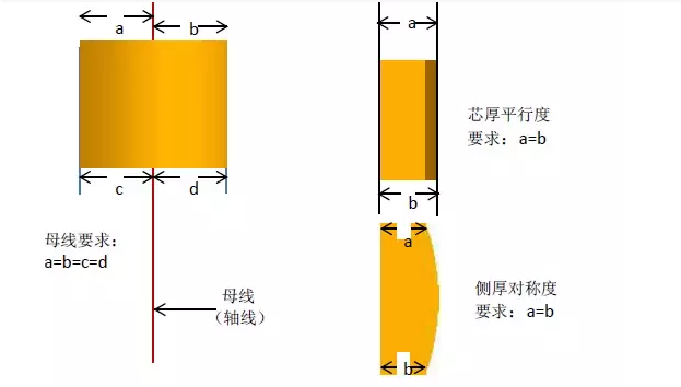

The cylindrical lens is a combination of two optical surfaces, and the relative position of two optical surfaces determines the overall optical properties of the cylindrical lens. So how to ensure the rationality of the relative position of two optical surfaces is the key and difficult point in the process of cylindrical lens. What is the ideal relationship between the two optical surfaces? Here is an example of the three views of a flat convex lens.

So in the process of cylindrical lens, if the relative position of two optical surface anomalies, common adverse project has the following kinds: (flat convex cylindrical lens, for example)

One. Bus bad


A: Bus offset: the cylindrical optic surface is offset by the cylinder axis opposite to the flat center. Here is the picture:
Causes and countermeasures:
1.The design or machine of fixture is defective, and the attached surface and the center line are not good. You need to start with the fixture.
2. The lens stick is not in place, need to be attached to the working method to begin to improve.
3. The product moves during processing. Need adhesive adhesion and processing time lens force load begin to improve.

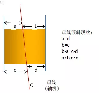
B: Bus tilt: the surface of the cylinder is tilted in a certain angle to the plane. The bus line is not parallel to the attached datum. Here is the picture:
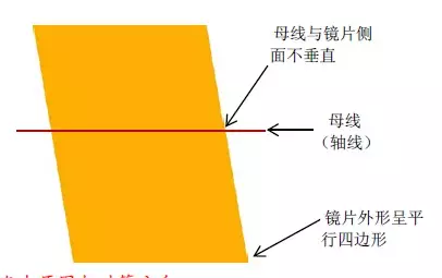

Causes and countermeasures:
1. The design or machine of fixture is defective, the surface of the lens is attached to the axis of the central axis and the failure of the channel is not good. You need to start with the fixture.
2. The lens stick is not in place, need to be attached to the working method to begin to improve.

Two. The bus is perpendicular to the line

Causes and countermeasures:
1. The design or machine of fixture is defective, and the two benchmarks are not straight. You need to start with the fixture.
2. The lens stick is not in place, need to be attached to the working method to begin to improve.
3. The cutting machine is not accurate, and the main shaft and the desktop are in the wrong angle. It is necessary to improve the machining accuracy. In accordance with stated in, cylinder lens bus location plays an important role in the optical performance, then the bus in addition to guarantee in the process of machining, in the test link is also very important. Here's a new way to detect a cylindrical lens:

Point laser reflection detector
Principle:
Using a laser generator through a special lens will be test cylinder lens, the light source into cylindrical lens by cylinder after receives the light source the light source is reflected back to image receiver, again by the CCD camera images appear on the display equipment. The final judgment is made by the testers.

Advantages:
High detection accuracy: the detection error can be controlled in 0.001 mm.
High detection efficiency: the skilled person can detect 20PCS per minute.
Do not affect the appearance: using laser reflection to detect has no direct contact to the surface of the product and to the product appearance does not have the effect.
New process of cylindrical lens processing
For a long time, most of the domestic cylindrical mirror manufacturing has been used in the traditional way of processing. It gradually failed to meet customers' needs. Our company is based on many years of lens processing experience, and study abroad advanced processing technology, the development of a set of advanced cylindrical lens to process the new method. This method changes the traditional single chip processing to make the plate processing, greatly improve the processing efficiency, and can reduce the processing cost. The stability of processing quality also increased significantly.

Labels: , , , , , ,

The benefits of aspheric lenses

Spherical aberration correction

The most significant benefit of a non-spherical lens is that it can be corrected for spherical aberrations. Spherical aberration is caused by using the surface of the sphere to focus or focus on the light. Therefore, in other words, all of the spherical surface, no matter whether there is any measurement error and manufacture error, will appear spherical aberration, as a result, they will need a not spherical or aspherical Lenses surfaces, carries on the correction. By adjusting the constant of the cone and non-spherical coefficients, any non-spherical lens can be optimized to minimize the image difference. For example, see figure 1, which shows a spherical lens with a significant spherical aberration, and a non-spherical lens with almost no spherical difference. The spherical difference in the spherical lens will allow the incoming light to focus at many different points, creating a blurred image. In a non-spherical lens, all the different light rays will focus on the same spot, resulting in less blurred and more quality images.

In order to better understand the aspheric lens and spherical lens in terms of focus performance difference, please refer to a quantitative model, in which we can observe two 25 mm diameter equal to the focal length of 25 mm lens (f / 1 lens). The following table compares on the shaft (0 °Angle) and outside the shaft(0.5 °and 1.0 °Angle) in parallel, monochromatic light (wavelength 587.6 nm) generate the light spot size or fuzzy.Spherical lenses are several orders of magnitude larger than non-spherical lenses.

The benefits of additional performance
Although the market also has many different techniques for correction by spherical aberration resulting from the surface, however, these other technology in the imaging performance and flexibility, are far less than aspheric lens offer. Another widely used technique involves increasing f / # by "reducing" lenses. While this improves the quality of the image, it also reduces the flux in the system, so there is a trade-off between the two.

On the other hand, when using aspheric lens, the additional aberration correction support users in the realization of high flux (low f / #, high numerical aperture) of the system design at the same time, still keep a good image quality. Higher luminous flux design causing image degradation can be sustainable, because a slightly reduced image quality performance will still be provided above the performance of the spherical system can provide. Consider a focal length of 81.5 mm, f / 2 triad lens (figure 2), the first is composed of three spherical surface, the second is one of the first surface of spherical surface (the rest) for spherical surface, the two design have exactly the same type of glass, effective focal length, field, f / #, as well as the overall length of the system. The following table is quantitatively compared with the axis of the modulation transfer function (MTF) at the @ 20% contrast and the parallel, multicolored 486.1 nanometers, 587.6 nm, and 656.3 nm rays. A triad of aspheric surface lens has been used, all on the viewing angle showed higher imaging performance, its high tangential and sagittal high resolution, compared with only the triad of spherical surface lens is three times higher.

Glass Precision Aspherical Lenses, IR Aspherical Lenses, Off-Axis Parabolic Mirrors


Optical Machining Centers

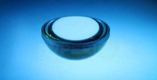
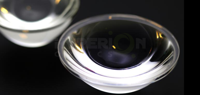
Due to the more complex surface profile of asphere which significantly reduces or eliminate optical aberrations as compared to the simple lens, Aspheric lenses have at least one surface that is not a true sphere,It has been more widely exploited in the lens optical design stage.


Using aspheres to replace a much more complex multi-element spherical system leads to the result of the optical device can be more compact, lighter, transmit more light and in certain cases be cost effective than the multi-lens spherical design.


At Hyperion Optics, we are equipped with Optotech asphere machine which offers our customers with contour deterministic micro grinding (CDMG) service, uses the accuracy and repeatability of a computer numerically controlled machine to grind the optical shape. We start by grinding the best-fit sphere to remove the bulk material and contour the aspheric shape into the optical material from edge to center. Typical materials available of our fabrication capability are optical glass, ZnSe, ZnS, BaF2, GaAs, and chalcogenide glass. We also accept materials supplied by customers.

Optical Machining Centers capability:

  • Capacities from 5mm to 400mm
  • 1000 to 24,000 rpm tool spindle
  • Automatic curve correction
  • Tool& Workpiece probing system
  • Dual tool spindles option


Following such manufacturing procedure, there is no extra investment on tooling and processing fixtures for sphere substrates and preparation, contributes customers a quick and productive start to the schedule. With the asphere part ground, the profilemeter measure will be conducted and transfer measured data to the polisher. In our polishing process, our experienced operators can control the asphere form error within 1 micron (Depends on the diameter of the parts).
Hyperion Optics values every single opportunity offered by customers; our typical MOQ is two pieces for optical performance approval purpose at customers’ end; Our fast asphere prototyping has become one of our most popular services for customer low ratio initial production LRIP projects. We can process both sphere and asphere parts at the same time for customer’s objective or eyepiece design, which secures a reliable timeline management to meet LRIP tight timing requirement. Meanwhile, we also provide coating package with competitive pricing serving this rapid prototyping concept.

Our rapid aspheric prototyping / LRIP service including:
1.When Off-the-shelf aspheric parts do not fit perfectly in your system, Hyperion Optics can design and manufacture the Precision aspheric lenses by your system-level optical requirement.
2.Built to print, Hyperion Optics fabricates aspheric lenses and provides inspection report by your print.
3.Reverse engineering based on samples you provide, Hyperion Optics runs in-depth mapping and optical performance testing on either aspheric lens part or lens system level products, redesign and optimize including manufacturing and assembly.
Please contact one of our a sphere experts today and find out what Hyperion Optics can help you with your projects.
Still finding aspheric lens manufacturers? Leave us a message now.

Asphere Lens manufacturing


Manufacturing Limits for Aspheric Surfaces
Based on Form Error Tolerance
Form Error > 2μm Lower Resolution Profilometry (2-D)1
Attribute
Minimum
Maximum
Diameter (mm)
3
250
Local Radius (mm)
-8 (Concave)
Sag (mm)
0
502
Departure (mm)
0.01
20
Included Angle (°)
0
120

Form Error 0.5 – 2μm Higher Resolution Profilometry (2-D)1
Attribute
Minimum
Maximum
Diameter (mm)3
3
250
Local Radius (mm)
-12 (Concave)
Sag (mm)
0
252
Departure (mm)
0.01
20
Included Angle (°)
0
150

Form Error < 0.5μm Interferometry with Stitching (3-D)
Attribute
Minimum
Maximum
Diameter (mm)3
3
250
Local Radius (mm)
-13 (Concave)
Sag (mm)
0
252,4
Departure (mm)
0.002
1
Included Angle (°)
0
120+5

Labels: , , , , , , , , ,

Beam Expander for sale, lens assembly


Beam expansion

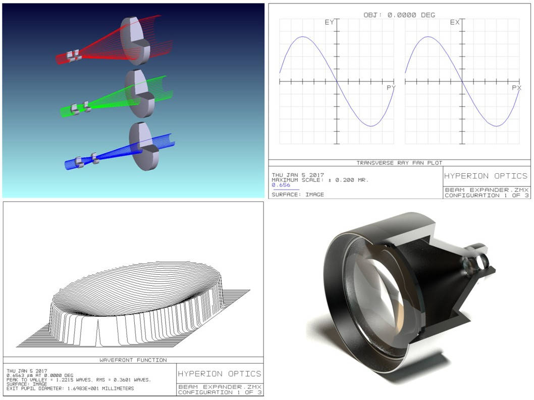
Beam expansion or reduction is a common application requirement in most labs using lasers or light sources and optics. Users always find there are so many off-the-shelf laser beam expanders, however, hard to find one exactly fit their needs in terms of spectral range or expansion ratio. In most cases, the plug and play solution may not be the answer.

Hyperion Optics helps customers with their unique expander
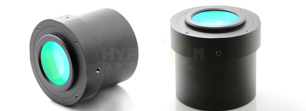
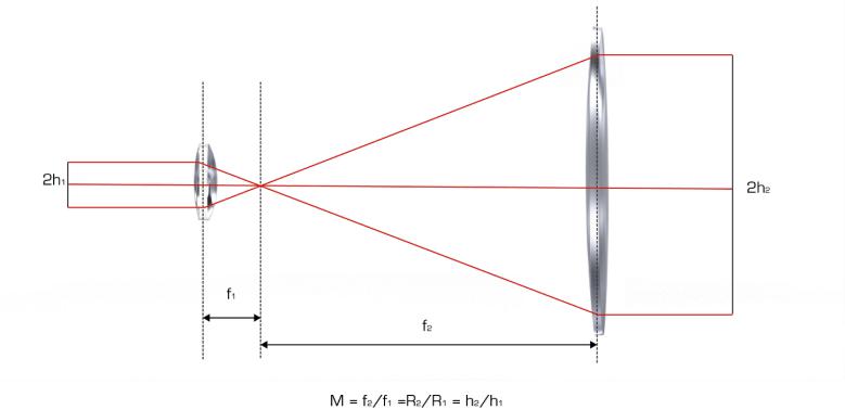
Hyperion Optics helps customers with their unique expander development project, from optical design, mechanical design and responsible for the application performance. It is critical to communicate with our engineers your input and output beam diameter ratio requirement. For simple expanders, such as telescopes, consists of two lenses, the magnification of a 2 lens system is equal to the ratio of the focal lengths of the lenses, which is also equal to the ratio of the radii of curvatures of the lenses.
unique expander for sale

M= the magnification of the beam expander
F2= effective focal length of exit lens
F1= effective focal length of entry lens
R2= radius of curvature of exit lens
H2=radius of exit spot (image height)
H1=radius of entry spot (object height)

At Hyperion Optics, we offer rapid optical design and prototyping, in most expander cases, we offer 6 weeks delivery, means when we study your application, expansion ratio and input output parameters, we are able to deliver assembled expander within 6 weeks. Or we can work on your existing off-the-shelf solution to improve your application’s performance.

We also offer off-the-shelf expanders, please refer to following products for your requirement, or contact our engineer for further information.

Part No.
Magnification
Input CA (mm)
Output CA (mm)
Thread
Max. Outer Dia (mm)
Length (mm)
HBE- 1064- 1.2X
1.2x
16
23
M22 x 0.75
29
54.9
HBE- 1064- 1.5X
1.5x
15.5
23
M22 x 0.75
25
44.5
HBE- 1064- 2X
2.0x
10
20
M22 x 0.75
26
42
HBE- 1064- 2.5X
2.5x
10
23
M22 x 0.75
29
79.8
HBE- 1064- 3X
3.0x
10
23
M22 x 0.75
29
58
HBE- 1064- 4X
4.0x
10
22
M22 x 0.75
29
81.1
HBE- 1064- 5X
5.0x
10
23
M22 x 0.75
29
72
HBE- 1064- 6X
6.0x
5
22
M22 x 0.75
29
71.2
HBE- 1064- 7X
7.0x
6
23
M22 x 0.75
29
76.4
HBE- 1064- 8X
8.0x
10
22
M22 x 0.75
29
76
HBE- 1064- 10X
10.0x
8
22
M22 x 0.75
29
69.7
HBE- 1064- 15X
15.0x
7.5
28
M30 x 1
45
99.1
HBE- 1064- 20X
20.0x
8
28
M22 x 0.75
45
91.2
Part No.
Magnification
Input CA (mm)
Output CA (mm)
Thread
Max. Outer Dia (mm)
Length (mm)
HBE- 633- 3X
3.0x
10
23
M22 x 0.75
33
63.7
HBE- 633- 5X
5.0x
8
23
M22 x 0.75
33
110
HBE- 633- 8X
8.0x
11
23.5
M28 x 0.55
35
117.5
HBE- 633- 10X
10.0x
8
23
M22 x 0.75
30
146
HBE- 633- 20X
20.0x
8
76
M22 x 0.75
30
198
HBE- 633- 40X
40.0x
8
100
M22 x 0.75
40
246
HBE- 633- 50X
50.0x
10
81
M22 x 0.75
30
304
Part No.
Magnification
Input CA (mm)
Output CA (mm)
Thread
Max. Outer Dia (mm)
Length (mm)
HBE- 532- 2X
2.0x
6
23
M22 x 0.75
30
83
HBE- 532- 3X
3.0x
6
23
M22 x 0.75
30
83
HBE- 532- 4X
4.0x
6
23
M22 x 0.75
30
83
HBE- 532- 5X
5.0x
8
24
M22 x 0.75
30
81.5
HBE- 532- 6X
6.0x
6
23
M22 x 0.75
30
83
HBE- 532- 10X
10.0x
6
23
M22 x 0.75
30
83
HBE- 532- 15X
15.0x
6
32
M30 x 1
30
85
HBE- 532- 20X
20.0x
6
38
M30 x 1
40
95.2
Part No.
Magnification
Input CA (mm)
Output CA (mm)
Thread
Max. Outer Dia (mm)
Length (mm)
HBE- 405-1.5X
1.5x
8
26
M30x1
46
62.3
HBE- 405-2X
2.0x
8
26
M30x1
46
62.3
HBE- 405-10X
10.0x
9
28
M30x1
46
85.6

Labels: , , , , , ,