Wednesday, November 8, 2017

The Application and Development of Cylindrical Lens in Modern Optoelectronic Products

The image monitoring and imaging devices currently being promoted provide us with an irreplaceable safety and comfort...
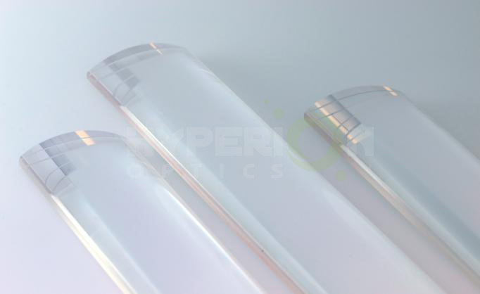
cylindrical lens 
Perhaps, while we are enjoying the convenience of optoelectronic products, we are ignoring the important components of the optoelectronic products, the cylindrical lens.

As we all know, Optoelectronic products are mostly composed of the light path system, electronics and mechanical systems. Light path system is considered to be crucial in the process of information collection and transmission. 

The optical system is composed of lenses, spectroscopes, and reflectors. The surface is usually a sphere or plane. The cylindrical lens is non-spherical, which can effectively reduce the ball difference and color difference. It is divided into flat convex cylindrical lens, flat concave cylindrical lens, double convex cylindrical lens and double concave cylindrical lens. It has one-dimensional amplification. Cylindrical lenses are designed to change the size of the image. For example, turn a spot of light into a patch or change the height of the image without changing the width. The special optical properties of the cylindrical lens make the cylindrical lens more and more widely used with the rapid development of high technology. Such as line gather system. films system. fax machines and printing typesetting scanning imaging system. And in the field of medical gastroscope. Laparoscopic, in the field of auto car video system with the participation of cylindrical lens. Linear detector at the same time in lighting, bar code scanning, holographic lighting, optical information processing, computer, laser emission. And the strong laser system and also has been widely used in synchrotron radiation beam line. At the same time, with the constant improvement of cylindrical lens processing technology, has formed a mature and effective processing technology, the quality of its good reproducibility and repeatability gradually been recognized by the market. At present, the process is gradually replacing the relatively backward traditional technology.

The cylindrical lens is known to consist of a flat and a concave (convex) surface or two concave (convex) surfaces. It can be divided into flat convex cylindrical lens, concave cylindrical lens, double convex cylindrical lens, double concave cylindrical lens, convex concave cylindrical lens. The shape is shown below:

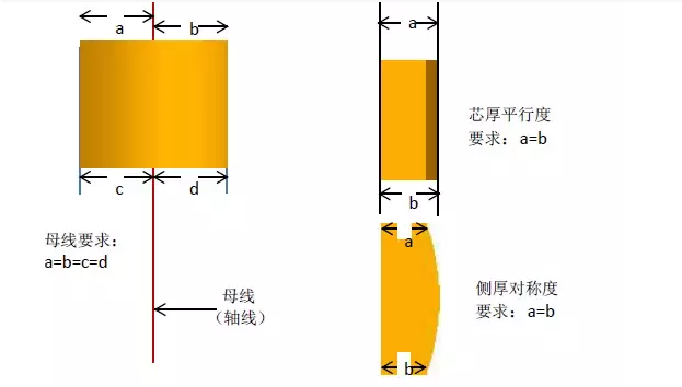

The cylindrical lens is a combination of two optical surfaces, and the relative position of two optical surfaces determines the overall optical properties of the cylindrical lens. So how to ensure the rationality of the relative position of two optical surfaces is the key and difficult point in the process of cylindrical lens. What is the ideal relationship between the two optical surfaces? Here is an example of the three views of a flat convex lens.

So in the process of cylindrical lens, if the relative position of two optical surface anomalies, common adverse project has the following kinds: (flat convex cylindrical lens, for example)

One. Bus bad


A: Bus offset: the cylindrical optic surface is offset by the cylinder axis opposite to the flat center. Here is the picture:
Causes and countermeasures:
1.The design or machine of fixture is defective, and the attached surface and the center line are not good. You need to start with the fixture.
2. The lens stick is not in place, need to be attached to the working method to begin to improve.
3. The product moves during processing. Need adhesive adhesion and processing time lens force load begin to improve.

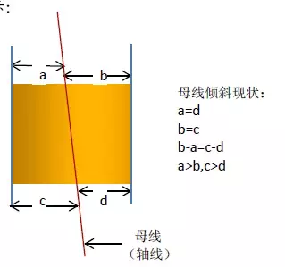
B: Bus tilt: the surface of the cylinder is tilted in a certain angle to the plane. The bus line is not parallel to the attached datum. Here is the picture:
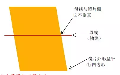

Causes and countermeasures:
1. The design or machine of fixture is defective, the surface of the lens is attached to the axis of the central axis and the failure of the channel is not good. You need to start with the fixture.
2. The lens stick is not in place, need to be attached to the working method to begin to improve.

Two. The bus is perpendicular to the line

Causes and countermeasures:
1. The design or machine of fixture is defective, and the two benchmarks are not straight. You need to start with the fixture.
2. The lens stick is not in place, need to be attached to the working method to begin to improve.
3. The cutting machine is not accurate, and the main shaft and the desktop are in the wrong angle. It is necessary to improve the machining accuracy. In accordance with stated in, cylinder lens bus location plays an important role in the optical performance, then the bus in addition to guarantee in the process of machining, in the test link is also very important. Here's a new way to detect a cylindrical lens:

Point laser reflection detector
Principle:
Using a laser generator through a special lens will be test cylinder lens, the light source into cylindrical lens by cylinder after receives the light source the light source is reflected back to image receiver, again by the CCD camera images appear on the display equipment. The final judgment is made by the testers.

Advantages:
High detection accuracy: the detection error can be controlled in 0.001 mm.
High detection efficiency: the skilled person can detect 20PCS per minute.
Do not affect the appearance: using laser reflection to detect has no direct contact to the surface of the product and to the product appearance does not have the effect.
New process of cylindrical lens processing
For a long time, most of the domestic cylindrical mirror manufacturing has been used in the traditional way of processing. It gradually failed to meet customers' needs. Our company is based on many years of lens processing experience, and study abroad advanced processing technology, the development of a set of advanced cylindrical lens to process the new method. This method changes the traditional single chip processing to make the plate processing, greatly improve the processing efficiency, and can reduce the processing cost. The stability of processing quality also increased significantly.

Labels: , , , , , ,

The Use of Cylindrical Lens

Cylindrical Lens can be used in a single axial convergence or divergence of the beam and found in optical measurement, laser scanning, spectroscopy, laser diode output beam shaping, the X-ray light microscopic imaging, and many other industries and fields have a wide range of applications.

Turn the quasi-direct light source into the line light source
L = 2(r0/f)(z+f)

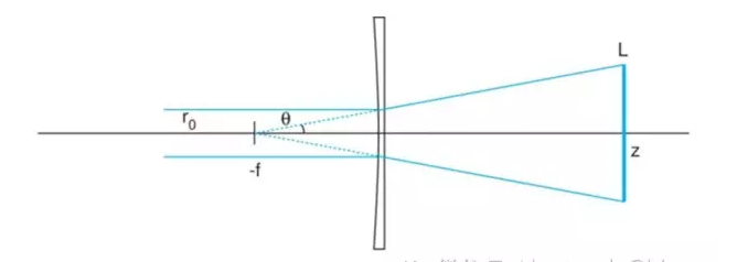
It is the most extensive application of cylindrical lens. As shown in the figure below, The quasi-direct light source with radius r0 is irradiated into a concave cylindrical lens with a focal length of -f(The image is in order to illustrate the principle more clearly, so amplify the beam radius). The beam will diverge in half theta (theta = r0 / f). At this point, it can also be approximated as the divergence of the point source at the focal point -f. The distance to the back of the lens is z. The width of the line beam is 2r0 (ignoring the divergence of the  Gaussian-distributed beam spot), but the length of the line beam is changed
L = 2 (r0 / f) (z + f)
When z is greater than f, the expansion ratio approaches z/f, and the length of the line is proportional to z.


application of cylindrical lens


If need in the z produces width is very narrow line light source, can be in the plane concave cylindrical lens front end or back end of a flat convex cylindrical lens focal length for z, with the orthogonal plane concave cylindrical lens place, to compress the beam width.

【 Quick Start】The focus and alignment of light

The diode outputs beam of collimation
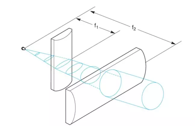
The laser diode output beam diverges in an asymmetric form, and its quasi-direct work is more challenging. for example, to divergence angle theta. Theta 1 x 2 = 10 ° x 40 ° diode light source, if only use the standard spherical lens, and only in a single direction on collimating, another direction divergence or convergence will happen. Using a cylindrical lens that the problem is decomposed into two one-dimensional directions, through the combination of two orthogonal cylinder lens, two directions can be collimated at the same time.


The selection of the cylindrical lens and the installation of the light road should follow the below rules:
θ1/θ2 = 10°/40° = f1/f2

1)To make the spot symmetrical after the adjustment, the focal length ratio of the two cylindrical lenses is equivalent to the divergence angle.
Theta 1 / theta 2 = 10°/ 40° = f1 / f2

2)The laser diode can be approximated as a point source, to get the collimating output, The spacing between the two cylinders and the light source is equal to the focal length of the two.

3)The spacing between the main planes of the two cylinders should be equal to the difference between the focal length of the f2-f1, and the actual spacing between the two lenses is equal to BFL2 - BFL1. Like the spherical lens, the convex side of a cylindrical mirror should be directed toward a quasi-direct beam to minimize as much as possible.
d1 = 2f1(tan(θ2/2))
d2 = 2f2(tan(θ1/2))

4)Because the laser diode output beam diverges faster, we need to be careful to confirm that the spot size on each cylinder is no longer than the effective light aperture of the lens. Because the distance of the cylinder is equal to its focal length, the maximum spot width of each cylinder should be followed
D1 = 2f1 (theta 2/2)
D2 is equal to 2f2, the tangent of theta one half.

For example, Newport CKX012 (f1 = 12.7 mm, BFL1 = 7.49 mm) and CKX050 (f2 = 50.2 mm, BFL2 = 46.03 mm) the combination of cylinder lens, the spacing between the two lens on the plane for BFL2 - BFL1 = 38.54 mm. The diameter of the spot in the first cylindrical lens is
D1 = 2 (12.7 mm) tan (20 °) = 9.2 mm
The diameter of the light spot in the second cylinder is
D2 = 2 (50.2 mm) tan (5 °) = 8.8 mm

Although there is still a little asymmetry, the simple combinations of these two cylindrical lenses have greatly improved the quality of the beams.

Hyperion Optics’ cylindrical components have been widely used for laser based applications with reliable optical performance and durability. We are able to provide Zygo report of all cylindrical surfaces we produce, and intensive measurement can be met upon customer’s request, such as optical axis deviation.

We are working closely to innovators and photography equipment designers who develop customized anamorphic systems where use cylindrical lenses as image aspect ratio changer.

For attach-on anamorphic lenses for smart phones, anamorphic cinema projection system, and front mounted anamorphic attachment. Please check out our anamorphic lenses for more information. If you are in the stage of developing your own anamorphic lenses, don’t hesitate contacting one of our optical engineers for free consultation to receive assistant from manufacturing perspective.

At Hyperion optics, we keep utilizing optical edging technique for most demanding requirement, which is essential in cylindrical component manufacturing. We provide full inspection data along with shipment including Zygo interferometry report and centering testing results.

Cylindrical lenses

Cylindrical lenses are used to focus, expand or condense light into a single dimension. Cylindrical lenses are widely used in laser scanners, optical information processing and computing, dye lasers or anamorphic lenses. Hyperion Optics has decade of cylindrical lenses manufacturing experience, ranging from ordinary plano-convex, plano-concave to cemented achromatic cylindrical lenses.

For most laser applications, Hyperion Optics’ cylindrical lenses offer always comes with competency in price; our monthly capability is 3,000 pcs. For prototyping quantity, we provide interferometry report along with the shipment upon request.

Hyperion Optics

In addition, Hyperion Optics has been working closely to innovators and photography equipment designers who develop customized anamorphic systems where use cylindrical lenses as image aspect ratio changer, such as attach-on anamorphic lenses for smart phones, anamorphic cinema projection system, and front mounted anamorphic attachment. Please check out our anamorphic lenses for more information. If you are in the stage of developing your own anamorphic lenses, don’t hesitate contacting one of our optical engineers for free consultation to receive assistant from manufacturing perspective.

At Hyperion optics, We keep utilizing optical edging technique for most demanding requirement, which is essential in cylindrical component manufacturing. We provide full inspection data along with shipment including Zygo interferometry report and centering testing results.

Cylindrical Lenses
COMMERCIAL GRADE
FACTORY STANDARD
PRECISION GRADE
Size Tolerance Length/Width(mm)
+0/-0.30
+0/-0.25
+0/-0.25
Diameter (mm)
+0/-0.15
+0/-0.10
±0.025
Wedge (along axis)
5 mrad
3 mrad
1 mrad
Focal Length Tolerance (%)
±2%
±2%
±1%
Cosmetic(MIL-C-13830A)
80-50
60-40
10-5
Irregularity (Lambda @ 632.8nm)
1 L
1/2 L
1/10 L
Centration (Arc min)
<5'
<3'
<1'
Coating (T% avg)
99%
99.5%
99.5%
Materials
Optical Glasses Depends On Design

Labels: , , , , , , ,

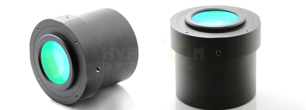
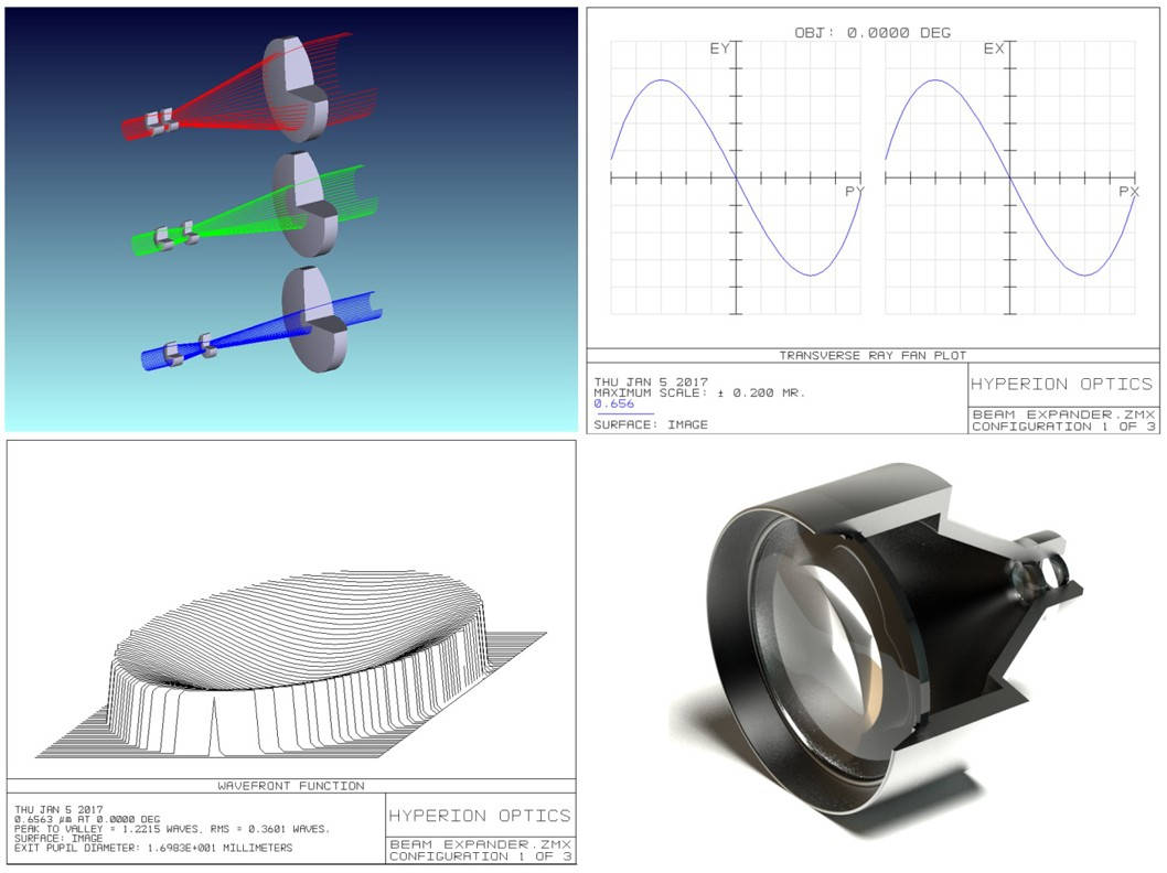
Beam Expander for sale, lens assembly


Beam expansion

Beam expansion or reduction is a common application requirement in most labs using lasers or light sources and optics. Users always find there are so many off-the-shelf laser beam expanders, however, hard to find one exactly fit their needs in terms of spectral range or expansion ratio. In most cases, the plug and play solution may not be the answer.

Hyperion Optics helps customers with their unique expander
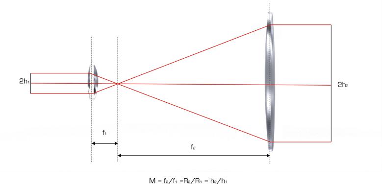
Hyperion Optics helps customers with their unique expander development project, from optical design, mechanical design and responsible for the application performance. It is critical to communicate with our engineers your input and output beam diameter ratio requirement. For simple expanders, such as telescopes, consists of two lenses, the magnification of a 2 lens system is equal to the ratio of the focal lengths of the lenses, which is also equal to the ratio of the radii of curvatures of the lenses.
unique expander for sale

M= the magnification of the beam expander
F2= effective focal length of exit lens
F1= effective focal length of entry lens
R2= radius of curvature of exit lens
H2=radius of exit spot (image height)
H1=radius of entry spot (object height)

At Hyperion Optics, we offer rapid optical design and prototyping, in most expander cases, we offer 6 weeks delivery, means when we study your application, expansion ratio and input output parameters, we are able to deliver assembled expander within 6 weeks. Or we can work on your existing off-the-shelf solution to improve your application’s performance.

We also offer off-the-shelf expanders, please refer to following products for your requirement, or contact our engineer for further information.

Part No.
Magnification
Input CA (mm)
Output CA (mm)
Thread
Max. Outer Dia (mm)
Length (mm)
HBE- 1064- 1.2X
1.2x
16
23
M22 x 0.75
29
54.9
HBE- 1064- 1.5X
1.5x
15.5
23
M22 x 0.75
25
44.5
HBE- 1064- 2X
2.0x
10
20
M22 x 0.75
26
42
HBE- 1064- 2.5X
2.5x
10
23
M22 x 0.75
29
79.8
HBE- 1064- 3X
3.0x
10
23
M22 x 0.75
29
58
HBE- 1064- 4X
4.0x
10
22
M22 x 0.75
29
81.1
HBE- 1064- 5X
5.0x
10
23
M22 x 0.75
29
72
HBE- 1064- 6X
6.0x
5
22
M22 x 0.75
29
71.2
HBE- 1064- 7X
7.0x
6
23
M22 x 0.75
29
76.4
HBE- 1064- 8X
8.0x
10
22
M22 x 0.75
29
76
HBE- 1064- 10X
10.0x
8
22
M22 x 0.75
29
69.7
HBE- 1064- 15X
15.0x
7.5
28
M30 x 1
45
99.1
HBE- 1064- 20X
20.0x
8
28
M22 x 0.75
45
91.2
Part No.
Magnification
Input CA (mm)
Output CA (mm)
Thread
Max. Outer Dia (mm)
Length (mm)
HBE- 633- 3X
3.0x
10
23
M22 x 0.75
33
63.7
HBE- 633- 5X
5.0x
8
23
M22 x 0.75
33
110
HBE- 633- 8X
8.0x
11
23.5
M28 x 0.55
35
117.5
HBE- 633- 10X
10.0x
8
23
M22 x 0.75
30
146
HBE- 633- 20X
20.0x
8
76
M22 x 0.75
30
198
HBE- 633- 40X
40.0x
8
100
M22 x 0.75
40
246
HBE- 633- 50X
50.0x
10
81
M22 x 0.75
30
304
Part No.
Magnification
Input CA (mm)
Output CA (mm)
Thread
Max. Outer Dia (mm)
Length (mm)
HBE- 532- 2X
2.0x
6
23
M22 x 0.75
30
83
HBE- 532- 3X
3.0x
6
23
M22 x 0.75
30
83
HBE- 532- 4X
4.0x
6
23
M22 x 0.75
30
83
HBE- 532- 5X
5.0x
8
24
M22 x 0.75
30
81.5
HBE- 532- 6X
6.0x
6
23
M22 x 0.75
30
83
HBE- 532- 10X
10.0x
6
23
M22 x 0.75
30
83
HBE- 532- 15X
15.0x
6
32
M30 x 1
30
85
HBE- 532- 20X
20.0x
6
38
M30 x 1
40
95.2
Part No.
Magnification
Input CA (mm)
Output CA (mm)
Thread
Max. Outer Dia (mm)
Length (mm)
HBE- 405-1.5X
1.5x
8
26
M30x1
46
62.3
HBE- 405-2X
2.0x
8
26
M30x1
46
62.3
HBE- 405-10X
10.0x
9
28
M30x1
46
85.6

Labels: , , , , , ,