Wednesday, November 8, 2017

The Application and Development of Cylindrical Lens in Modern Optoelectronic Products
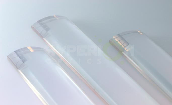
The image monitoring and imaging devices currently being promoted provide us with an irreplaceable safety and comfort...
cylindrical lens 
Perhaps, while we are enjoying the convenience of optoelectronic products, we are ignoring the important components of the optoelectronic products, the cylindrical lens.

As we all know, Optoelectronic products are mostly composed of the light path system, electronics and mechanical systems. Light path system is considered to be crucial in the process of information collection and transmission. 

The optical system is composed of lenses, spectroscopes, and reflectors. The surface is usually a sphere or plane. The cylindrical lens is non-spherical, which can effectively reduce the ball difference and color difference. It is divided into flat convex cylindrical lens, flat concave cylindrical lens, double convex cylindrical lens and double concave cylindrical lens. It has one-dimensional amplification. Cylindrical lenses are designed to change the size of the image. For example, turn a spot of light into a patch or change the height of the image without changing the width. The special optical properties of the cylindrical lens make the cylindrical lens more and more widely used with the rapid development of high technology. Such as line gather system. films system. fax machines and printing typesetting scanning imaging system. And in the field of medical gastroscope. Laparoscopic, in the field of auto car video system with the participation of cylindrical lens. Linear detector at the same time in lighting, bar code scanning, holographic lighting, optical information processing, computer, laser emission. And the strong laser system and also has been widely used in synchrotron radiation beam line. At the same time, with the constant improvement of cylindrical lens processing technology, has formed a mature and effective processing technology, the quality of its good reproducibility and repeatability gradually been recognized by the market. At present, the process is gradually replacing the relatively backward traditional technology.

The cylindrical lens is known to consist of a flat and a concave (convex) surface or two concave (convex) surfaces. It can be divided into flat convex cylindrical lens, concave cylindrical lens, double convex cylindrical lens, double concave cylindrical lens, convex concave cylindrical lens. The shape is shown below:

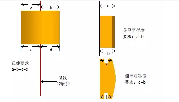

The cylindrical lens is a combination of two optical surfaces, and the relative position of two optical surfaces determines the overall optical properties of the cylindrical lens. So how to ensure the rationality of the relative position of two optical surfaces is the key and difficult point in the process of cylindrical lens. What is the ideal relationship between the two optical surfaces? Here is an example of the three views of a flat convex lens.

So in the process of cylindrical lens, if the relative position of two optical surface anomalies, common adverse project has the following kinds: (flat convex cylindrical lens, for example)

One. Bus bad


A: Bus offset: the cylindrical optic surface is offset by the cylinder axis opposite to the flat center. Here is the picture:
Causes and countermeasures:
1.The design or machine of fixture is defective, and the attached surface and the center line are not good. You need to start with the fixture.
2. The lens stick is not in place, need to be attached to the working method to begin to improve.
3. The product moves during processing. Need adhesive adhesion and processing time lens force load begin to improve.

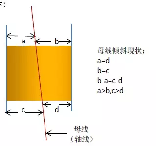
B: Bus tilt: the surface of the cylinder is tilted in a certain angle to the plane. The bus line is not parallel to the attached datum. Here is the picture:
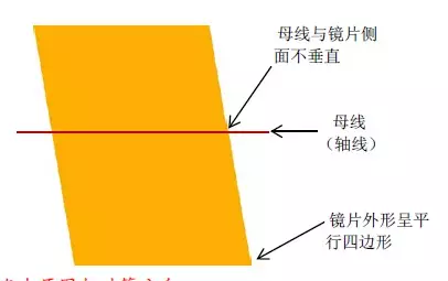

Causes and countermeasures:
1. The design or machine of fixture is defective, the surface of the lens is attached to the axis of the central axis and the failure of the channel is not good. You need to start with the fixture.
2. The lens stick is not in place, need to be attached to the working method to begin to improve.

Two. The bus is perpendicular to the line

Causes and countermeasures:
1. The design or machine of fixture is defective, and the two benchmarks are not straight. You need to start with the fixture.
2. The lens stick is not in place, need to be attached to the working method to begin to improve.
3. The cutting machine is not accurate, and the main shaft and the desktop are in the wrong angle. It is necessary to improve the machining accuracy. In accordance with stated in, cylinder lens bus location plays an important role in the optical performance, then the bus in addition to guarantee in the process of machining, in the test link is also very important. Here's a new way to detect a cylindrical lens:

Point laser reflection detector
Principle:
Using a laser generator through a special lens will be test cylinder lens, the light source into cylindrical lens by cylinder after receives the light source the light source is reflected back to image receiver, again by the CCD camera images appear on the display equipment. The final judgment is made by the testers.

Advantages:
High detection accuracy: the detection error can be controlled in 0.001 mm.
High detection efficiency: the skilled person can detect 20PCS per minute.
Do not affect the appearance: using laser reflection to detect has no direct contact to the surface of the product and to the product appearance does not have the effect.
New process of cylindrical lens processing
For a long time, most of the domestic cylindrical mirror manufacturing has been used in the traditional way of processing. It gradually failed to meet customers' needs. Our company is based on many years of lens processing experience, and study abroad advanced processing technology, the development of a set of advanced cylindrical lens to process the new method. This method changes the traditional single chip processing to make the plate processing, greatly improve the processing efficiency, and can reduce the processing cost. The stability of processing quality also increased significantly.

Labels: , , , , , ,

The Use of Cylindrical Lens

Cylindrical Lens can be used in a single axial convergence or divergence of the beam and found in optical measurement, laser scanning, spectroscopy, laser diode output beam shaping, the X-ray light microscopic imaging, and many other industries and fields have a wide range of applications.

Turn the quasi-direct light source into the line light source
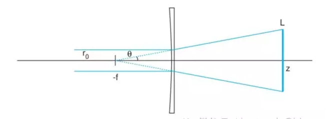
L = 2(r0/f)(z+f)

It is the most extensive application of cylindrical lens. As shown in the figure below, The quasi-direct light source with radius r0 is irradiated into a concave cylindrical lens with a focal length of -f(The image is in order to illustrate the principle more clearly, so amplify the beam radius). The beam will diverge in half theta (theta = r0 / f). At this point, it can also be approximated as the divergence of the point source at the focal point -f. The distance to the back of the lens is z. The width of the line beam is 2r0 (ignoring the divergence of the  Gaussian-distributed beam spot), but the length of the line beam is changed
L = 2 (r0 / f) (z + f)
When z is greater than f, the expansion ratio approaches z/f, and the length of the line is proportional to z.


application of cylindrical lens


If need in the z produces width is very narrow line light source, can be in the plane concave cylindrical lens front end or back end of a flat convex cylindrical lens focal length for z, with the orthogonal plane concave cylindrical lens place, to compress the beam width.

【 Quick Start】The focus and alignment of light

The diode outputs beam of collimation
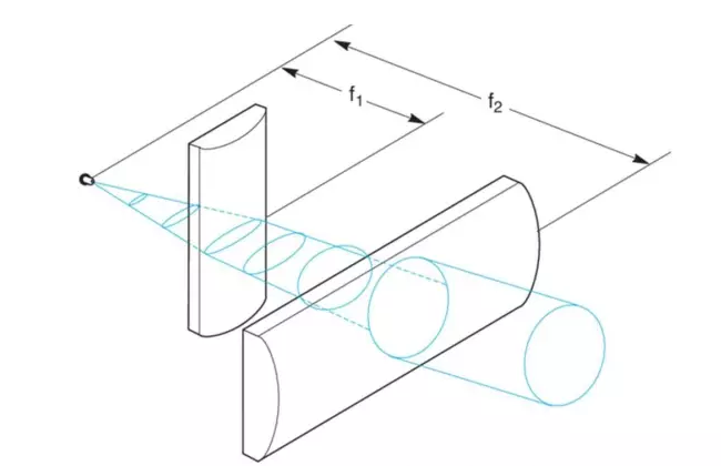
The laser diode output beam diverges in an asymmetric form, and its quasi-direct work is more challenging. for example, to divergence angle theta. Theta 1 x 2 = 10 ° x 40 ° diode light source, if only use the standard spherical lens, and only in a single direction on collimating, another direction divergence or convergence will happen. Using a cylindrical lens that the problem is decomposed into two one-dimensional directions, through the combination of two orthogonal cylinder lens, two directions can be collimated at the same time.


The selection of the cylindrical lens and the installation of the light road should follow the below rules:
θ1/θ2 = 10°/40° = f1/f2

1)To make the spot symmetrical after the adjustment, the focal length ratio of the two cylindrical lenses is equivalent to the divergence angle.
Theta 1 / theta 2 = 10°/ 40° = f1 / f2

2)The laser diode can be approximated as a point source, to get the collimating output, The spacing between the two cylinders and the light source is equal to the focal length of the two.

3)The spacing between the main planes of the two cylinders should be equal to the difference between the focal length of the f2-f1, and the actual spacing between the two lenses is equal to BFL2 - BFL1. Like the spherical lens, the convex side of a cylindrical mirror should be directed toward a quasi-direct beam to minimize as much as possible.
d1 = 2f1(tan(θ2/2))
d2 = 2f2(tan(θ1/2))

4)Because the laser diode output beam diverges faster, we need to be careful to confirm that the spot size on each cylinder is no longer than the effective light aperture of the lens. Because the distance of the cylinder is equal to its focal length, the maximum spot width of each cylinder should be followed
D1 = 2f1 (theta 2/2)
D2 is equal to 2f2, the tangent of theta one half.

For example, Newport CKX012 (f1 = 12.7 mm, BFL1 = 7.49 mm) and CKX050 (f2 = 50.2 mm, BFL2 = 46.03 mm) the combination of cylinder lens, the spacing between the two lens on the plane for BFL2 - BFL1 = 38.54 mm. The diameter of the spot in the first cylindrical lens is
D1 = 2 (12.7 mm) tan (20 °) = 9.2 mm
The diameter of the light spot in the second cylinder is
D2 = 2 (50.2 mm) tan (5 °) = 8.8 mm

Although there is still a little asymmetry, the simple combinations of these two cylindrical lenses have greatly improved the quality of the beams.

Hyperion Optics’ cylindrical components have been widely used for laser based applications with reliable optical performance and durability. We are able to provide Zygo report of all cylindrical surfaces we produce, and intensive measurement can be met upon customer’s request, such as optical axis deviation.

We are working closely to innovators and photography equipment designers who develop customized anamorphic systems where use cylindrical lenses as image aspect ratio changer.

For attach-on anamorphic lenses for smart phones, anamorphic cinema projection system, and front mounted anamorphic attachment. Please check out our anamorphic lenses for more information. If you are in the stage of developing your own anamorphic lenses, don’t hesitate contacting one of our optical engineers for free consultation to receive assistant from manufacturing perspective.

At Hyperion optics, we keep utilizing optical edging technique for most demanding requirement, which is essential in cylindrical component manufacturing. We provide full inspection data along with shipment including Zygo interferometry report and centering testing results.

Cylindrical lenses

Cylindrical lenses are used to focus, expand or condense light into a single dimension. Cylindrical lenses are widely used in laser scanners, optical information processing and computing, dye lasers or anamorphic lenses. Hyperion Optics has decade of cylindrical lenses manufacturing experience, ranging from ordinary plano-convex, plano-concave to cemented achromatic cylindrical lenses.

For most laser applications, Hyperion Optics’ cylindrical lenses offer always comes with competency in price; our monthly capability is 3,000 pcs. For prototyping quantity, we provide interferometry report along with the shipment upon request.

Hyperion Optics

In addition, Hyperion Optics has been working closely to innovators and photography equipment designers who develop customized anamorphic systems where use cylindrical lenses as image aspect ratio changer, such as attach-on anamorphic lenses for smart phones, anamorphic cinema projection system, and front mounted anamorphic attachment. Please check out our anamorphic lenses for more information. If you are in the stage of developing your own anamorphic lenses, don’t hesitate contacting one of our optical engineers for free consultation to receive assistant from manufacturing perspective.

At Hyperion optics, We keep utilizing optical edging technique for most demanding requirement, which is essential in cylindrical component manufacturing. We provide full inspection data along with shipment including Zygo interferometry report and centering testing results.

Cylindrical Lenses
COMMERCIAL GRADE
FACTORY STANDARD
PRECISION GRADE
Size Tolerance Length/Width(mm)
+0/-0.30
+0/-0.25
+0/-0.25
Diameter (mm)
+0/-0.15
+0/-0.10
±0.025
Wedge (along axis)
5 mrad
3 mrad
1 mrad
Focal Length Tolerance (%)
±2%
±2%
±1%
Cosmetic(MIL-C-13830A)
80-50
60-40
10-5
Irregularity (Lambda @ 632.8nm)
1 L
1/2 L
1/10 L
Centration (Arc min)
<5'
<3'
<1'
Coating (T% avg)
99%
99.5%
99.5%
Materials
Optical Glasses Depends On Design

Labels: , , , , , , ,

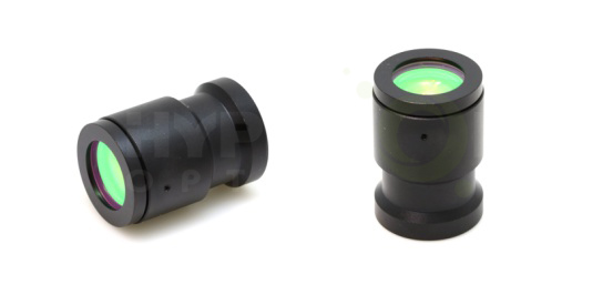
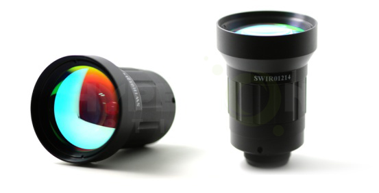
SWIR Lenses pictures and specifications

Hyperion Optics SWIR lens

Shortwave Infrared wavelength band offers a unique imaging advantages over visible and other thermal bands. So it is quietly earning a growing place in industrial machine vision for quality inspection and in military applications. SWIR lenses are utilized where other detectors or cameras are not sensitive enough for the finite detail recognition. At Hyperion Optics, we have developed a series of SWIR lenses to meet the latest advancement of SWIR technology. Our design is for high-resolution operation at low light level. It also offers a superior image quality, better transmission, and performance. Our SWIR lenses function in the wavelengths of 900nm-1700nm / 700nm-3400nm with the detector size up to 20mm diagonal and pixel size of 15-50μm.

SWIR lenses
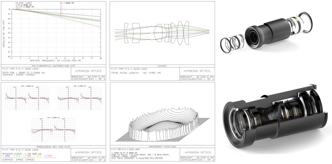
Apart from off-the-shelf SWIR optics, Hyperion Optics offers custom SWIR system design, for glass selection, We offer Schott / OHARA based glass choices and has a wide range of Schott and OHARA molded substrates inventory in various diameter and CT which assist us to greatly lower down your investment on glass materials. further to minimize your investment, we offer actual tested refractive index and dispersion testing on CDGM and NHG material equivalents through 0.7μm to 2.5μm for a better performance optimizing at the lowest price. We also can disclose our internal material refractive index and dispersion test data (with correspondent materials stock) for designers to develop your own SWIR system upon request. Glass witness samples can be provided free of charge for index and dispersion testing on customers'side too.

Please talk to one of our experienced optical designers to know how it works.

 custom SWIR system design

For custom SWIR design, we encourage the customer to choose materials from NHG for cost-wise decision if your budgetary is tight. Please contact us for latest NHG glass catalog update, since NHG is keeping releasing new refractive index and dispersion data through VIS to 2500nm periodically.

Our custom SWIR prototyping project starts from 2 to 5 sets. For applications such as hyperspectral CCD spectrometer, we also work with customer’s design as a build to print, further to provide assembly and test service. (Including wavefront error, MTF, Transmission etc.)

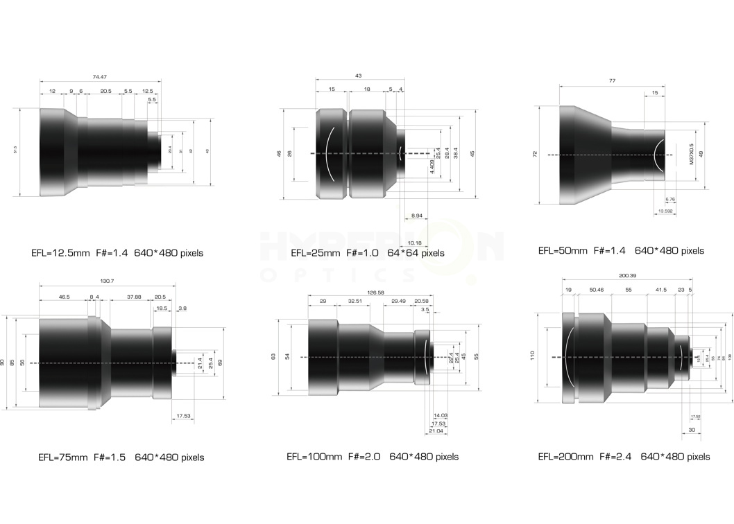
Off-The-Shelf SWIR Lenses
Opto-Mechanical PropertySpecification
Focal Length12.5 mm25 mm50 mm75 mm100 mm200 mm32.4 mm25 mm100 mm
F#1.41.41.41.52.02.41.02.02.0
Wavelength0.7 μm - 1.9 μm0.9μm - 1.7μm0.9μm - 1.7 μm0.9 μm - 1.7 μm0.9 μm - 1.7 μm0.9 μm - 1.7 μm1 μm - 3 μm1.2 μm - 3.4 μm1.5 μm-5 μm
Image Diagonal16 mm20 mm20 mm20 mm20 mm20 mm-3.2 mm12.3 mm
Average Transmission> 85%> 90%> 90%> 90%> 90%> 90%> 85%> 90%> 90%
Circular FOV67.7º43.6º22.6º15.2º11.4º5.7º2.5º7.3º
Back Focus Distance12.6 mm13.526 mm21.76 mm17.53 mm17.53 mm17.526 mm-12.94 mm59 mm
Back Working Distance2.75 mm4.383 mm6.76 mm13.73 mm14.03 mm12.526 mm10 mm8.94 mm54 mm
DimensionLength 82 mm, Φ45 mmLength 53.5 mm, Φ63 mmLength 77 mm, Φ72 mmLength 130.7 mm, Φ90 mmLength 126.58 mm, Φ63 mmLength 200.39 mm, Φ110 mmLength 24 mm, Φ41 mmLength 43 mm, Φ46 mmLength 97 mm, Φ110 mm
Focus TypeManual FocusManual FocusManual FocusManual FocusManual FocusManual FocusFixed FocusManual FocusManual Focus
Focus Range-1 m to infinity1 m to infinity2 m to infinity2 m to infinity2 m to infinity-2 m to infinity2 m to infinity
Mount TypeM 35.5 * 0.525.4 - 32 TPIM 37 * 0.525.4 - 32 teeth / inch25.4 - 32 teeth / inch25.4 - 32 teeth / inchM 41 * 0.7525.4 - 32 teeth / inchM 70 * 1
Detector640 * 480 pixels, 25 μm640 * 480 pixels, 25 μm640 * 480 pixels, 25 μm640 * 480 pixels, 25 μm640 * 480 pixels, 25 μm640 * 480 pixels, 25 μm-64 * 64 pixels, 50 μm640 * 512 pixels, 15 μm
Environmental
Operating Temperature- 20℃ to + 60℃
Storage Temperature- 40℃ to + 80℃
External CoatingAR
Humidity100% RH at 26℃ and 74% RH at 35℃ for 24 hours

If you need further SWIR optics technical support please contact us.

Labels: , , , , ,

The benefits of aspheric lenses

Spherical aberration correction

The most significant benefit of a non-spherical lens is that it can be corrected for spherical aberrations. Spherical aberration is caused by using the surface of the sphere to focus or focus on the light. Therefore, in other words, all of the spherical surface, no matter whether there is any measurement error and manufacture error, will appear spherical aberration, as a result, they will need a not spherical or aspherical Lenses surfaces, carries on the correction. By adjusting the constant of the cone and non-spherical coefficients, any non-spherical lens can be optimized to minimize the image difference. For example, see figure 1, which shows a spherical lens with a significant spherical aberration, and a non-spherical lens with almost no spherical difference. The spherical difference in the spherical lens will allow the incoming light to focus at many different points, creating a blurred image. In a non-spherical lens, all the different light rays will focus on the same spot, resulting in less blurred and more quality images.

In order to better understand the aspheric lens and spherical lens in terms of focus performance difference, please refer to a quantitative model, in which we can observe two 25 mm diameter equal to the focal length of 25 mm lens (f / 1 lens). The following table compares on the shaft (0 °Angle) and outside the shaft(0.5 °and 1.0 °Angle) in parallel, monochromatic light (wavelength 587.6 nm) generate the light spot size or fuzzy.Spherical lenses are several orders of magnitude larger than non-spherical lenses.

The benefits of additional performance
Although the market also has many different techniques for correction by spherical aberration resulting from the surface, however, these other technology in the imaging performance and flexibility, are far less than aspheric lens offer. Another widely used technique involves increasing f / # by "reducing" lenses. While this improves the quality of the image, it also reduces the flux in the system, so there is a trade-off between the two.

On the other hand, when using aspheric lens, the additional aberration correction support users in the realization of high flux (low f / #, high numerical aperture) of the system design at the same time, still keep a good image quality. Higher luminous flux design causing image degradation can be sustainable, because a slightly reduced image quality performance will still be provided above the performance of the spherical system can provide. Consider a focal length of 81.5 mm, f / 2 triad lens (figure 2), the first is composed of three spherical surface, the second is one of the first surface of spherical surface (the rest) for spherical surface, the two design have exactly the same type of glass, effective focal length, field, f / #, as well as the overall length of the system. The following table is quantitatively compared with the axis of the modulation transfer function (MTF) at the @ 20% contrast and the parallel, multicolored 486.1 nanometers, 587.6 nm, and 656.3 nm rays. A triad of aspheric surface lens has been used, all on the viewing angle showed higher imaging performance, its high tangential and sagittal high resolution, compared with only the triad of spherical surface lens is three times higher.

Glass Precision Aspherical Lenses, IR Aspherical Lenses, Off-Axis Parabolic Mirrors


Optical Machining Centers

Due to the more complex surface profile of asphere which significantly reduces or eliminate optical aberrations as compared to the simple lens, Aspheric lenses have at least one surface that is not a true sphere,It has been more widely exploited in the lens optical design stage.


Using aspheres to replace a much more complex multi-element spherical system leads to the result of the optical device can be more compact, lighter, transmit more light and in certain cases be cost effective than the multi-lens spherical design.


At Hyperion Optics, we are equipped with Optotech asphere machine which offers our customers with contour deterministic micro grinding (CDMG) service, uses the accuracy and repeatability of a computer numerically controlled machine to grind the optical shape. We start by grinding the best-fit sphere to remove the bulk material and contour the aspheric shape into the optical material from edge to center. Typical materials available of our fabrication capability are optical glass, ZnSe, ZnS, BaF2, GaAs, and chalcogenide glass. We also accept materials supplied by customers.

Optical Machining Centers capability:

  • Capacities from 5mm to 400mm
  • 1000 to 24,000 rpm tool spindle
  • Automatic curve correction
  • Tool& Workpiece probing system
  • Dual tool spindles option


Following such manufacturing procedure, there is no extra investment on tooling and processing fixtures for sphere substrates and preparation, contributes customers a quick and productive start to the schedule. With the asphere part ground, the profilemeter measure will be conducted and transfer measured data to the polisher. In our polishing process, our experienced operators can control the asphere form error within 1 micron (Depends on the diameter of the parts).
Hyperion Optics values every single opportunity offered by customers; our typical MOQ is two pieces for optical performance approval purpose at customers’ end; Our fast asphere prototyping has become one of our most popular services for customer low ratio initial production LRIP projects. We can process both sphere and asphere parts at the same time for customer’s objective or eyepiece design, which secures a reliable timeline management to meet LRIP tight timing requirement. Meanwhile, we also provide coating package with competitive pricing serving this rapid prototyping concept.

Our rapid aspheric prototyping / LRIP service including:
1.When Off-the-shelf aspheric parts do not fit perfectly in your system, Hyperion Optics can design and manufacture the Precision aspheric lenses by your system-level optical requirement.
2.Built to print, Hyperion Optics fabricates aspheric lenses and provides inspection report by your print.
3.Reverse engineering based on samples you provide, Hyperion Optics runs in-depth mapping and optical performance testing on either aspheric lens part or lens system level products, redesign and optimize including manufacturing and assembly.
Please contact one of our a sphere experts today and find out what Hyperion Optics can help you with your projects.
Still finding aspheric lens manufacturers? Leave us a message now.

Asphere Lens manufacturing


Manufacturing Limits for Aspheric Surfaces
Based on Form Error Tolerance
Form Error > 2μm Lower Resolution Profilometry (2-D)1
Attribute
Minimum
Maximum
Diameter (mm)
3
250
Local Radius (mm)
-8 (Concave)
Sag (mm)
0
502
Departure (mm)
0.01
20
Included Angle (°)
0
120

Form Error 0.5 – 2μm Higher Resolution Profilometry (2-D)1
Attribute
Minimum
Maximum
Diameter (mm)3
3
250
Local Radius (mm)
-12 (Concave)
Sag (mm)
0
252
Departure (mm)
0.01
20
Included Angle (°)
0
150

Form Error < 0.5μm Interferometry with Stitching (3-D)
Attribute
Minimum
Maximum
Diameter (mm)3
3
250
Local Radius (mm)
-13 (Concave)
Sag (mm)
0
252,4
Departure (mm)
0.002
1
Included Angle (°)
0
120+5

Labels: , , , , , , , , ,